 |
| September 16, 2014 | Volume 10 Issue 35 |
Designfax weekly eMagazine

Archives
Partners
Manufacturing Center
Product Spotlight
Modern Applications News
Metalworking Ideas For
Today's Job Shops
Tooling and Production
Strategies for large
metalworking plants
Engineer's Toolbox Military:
High-performance thermal management solutions for LEDs
By Nelson J. Gernert, Vice President, Engineering and Technology;
Dr. Mark T. North, Engineering Group Leader - Research and Development;
and Gregg J. Baldassarre - Vice President, Sales and Marketing, Thermacore
When it comes to high-power lighting applications in the military and harsh industrial environments, reliability and efficiency are key features for design engineers to consider. To maximize both of these qualities, light-emitting diode (LED) lighting technology is coming in to play with brighter, more flexible lighting solutions. LEDs are longer lasting, appear brighter, and are more versatile and more durable than incandescent and compact fluorescent lighting (CFL), making them a logical choice for many lighting needs in the military harsh industrial environments.
The quality of the light and the lifetime reliability of LEDs are both temperature dependent, so thermal management is critical for maximizing LED output. Because LEDs are semiconductors, they emit a substantial amount of waste heat in a very small area. As a result, designers must consider the most appropriate thermal management solutions that can collect the highly concentrated waste heat and then move or dissipate the heat.
Effectively managing the LED waste heat will enable the LED to maintain acceptable operating temperatures and quality of light, while at the same time maximizing operating life. In addition, due to the fact that military, industrial, and consumer applications of LED lighting necessitate small, compact packaging, space or volume is always at a premium, requiring the LED cooling approaches to be configurable to accommodate various packaging constraints. For example, sometimes it is necessary to route the heat away from the source and dissipate it remotely.
Military technology is moving toward an increasing trend of miniaturization, and smart resource utilization and cost efficiency are always priorities. LEDs with optimized thermal management solutions are a natural fit for many military applications.
Thermal management options
Designers have several options to keep LEDs cool using passive thermal management technologies, such as heat pipe-based assemblies or k-Core Encapsulated annealed pyrolytic graphite (APG). These passive thermal management technologies help LED manufacturers protect sensitive electronic devices and ensure the high performance that gives LEDs an edge over other options like incandescent and CFLs.
Some constraints, including limited height budget and the need for reduced or no electrical power consumption or noise, make heat pipe-based thermal solutions especially attractive. Low maintenance requirements, increased product reliability, better light quality, and sealed enclosure cooling are other project considerations that make heat pipes an ideal option.
The selection of the proper heat pipe cooling solution is dependent upon each customer's specifications and design constraints. For example, a natural convection cooling solution involves rejecting heat to the ambient environment by natural convection, i.e., no fans. This is typically very difficult to do when considering LEDs, except when heat pipes are used. Figure 1 illustrates an LED cooling design that uses heat pipes to contact the LEDs directly. The heat pipe transports the heat to multiple thin plate fins that are spaced properly to allow the air to circulate naturally regardless of the orientation of the LEDs. The configuration of the fin stack is variable.
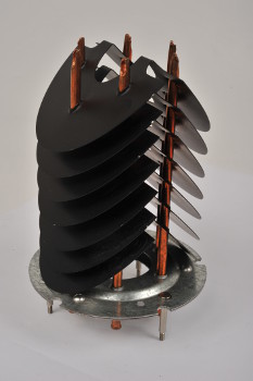
Figure 1: Natural convection heat pipe heat sink for LED cooling.
In many conventional systems, LED electronic devices are mounted on copper alloy substrates using soft or hard die attach. While these copper alloy substrates are inexpensive and reliable, they possess thermal conductivity properties that are about 50 percent that of copper, or 200 W/(m.K). More favorably, copper alloy substrates have a Coefficient of Thermal Expansion (CTE) that is closer in value to various LED semiconductor materials than more traditional thermal management materials such as pure copper and aluminum. As opposed to a heat pipe system that relies on two-phase heat transfer through the evaporation and condensation of a working fluid, copper alloy substrates rely on solid conduction heat transfer, and as a result, the distance that these copper alloy materials can transport heat with a given temperature difference is very limited. Another disadvantage of copper alloy solid materials is mass, as these solutions may add significant mass to the overall system. Using a solid conductor like diamond can improve thermal conductivity and CTE matching, but a diamond-based solution is very expensive. The optimum approach is a replacement material or system that has a high thermal conductivity and a matching CTE at a reasonable cost.
Heat pipes and heat pipe thermal ground planes (TGPs)
Heat pipes typically have three components: a vacuum-tight, sealed containment shell or vessel, working fluid, and a capillary wick structure. The traditional heat pipe is a cylindrical tube that transfers thermal energy from a heat-generating source, such as an LED, through its collection of the heat into the evaporator section of the heat pipe, and then movement of the heat by the working fluid vapor flow to the heat pipe condenser section, where the working fluid condenses and releases the heat to a cooling medium, such as the ambient air, a circulated liquid, or a cold plate for final dissipation. Typically, the heat flux is reduced in the condenser section, facilitating heat transfer to traditionally less capable media such as air. The capillary wick structure allows the heat pipe to develop the capillary action for the returning liquid from the condenser to the evaporator.
For most electronics cooling applications, water is the most commonly used working fluid; other working fluids can be used in applications requiring operation at unusually high temperature (>300 deg C) or low temperatures (<0 deg C). Capillary wick structures have many configurations, with typical structures being internal grooves, wire or screen mesh, and sintered powder metal. Sintered powder metal offers the most advantages in terms of capillary pumping capability for long-distance transport, heat flux capacity, freeze/thaw tolerance, and high gravitational or acceleration environments.
Heat pipes have been successfully used in various types of military, computer, and medical electronic systems for decades. For example, heat pipe-based thermal solutions are used in "mission critical" military radar electronics, military power conversion, avionics, and satellite thermal control applications. Heat pipes are bendable, flexible, routable, and have proven reliable under demanding conditions such as high-g (i.e, gravity up to 10-g), shock/vibration, and freeze/thaw (1,600 temperature cycles from -40 deg C to +90 deg C) requirements typical of military and aerospace applications. To increase customization, working fluid and casing/envelope materials can also be bent and formed to fit custom applications.
LED electronic components may be directly attached to heat pipe thermal ground planes (TGPs). TGPs are thin, flat, or planar heat pipes, typically 1-mm to 3-mm thick. The planner geometry facilitates attachment of flat electronic devices such as LEDs by epoxy or solder bonding. Direct attachment of the TGP to the LED has the added benefit of minimizing thermal interfaces. Figure 2 is a typical heat pipe TGP. A TGP such as the unit shown requires less than 1 gram of fluid and spreads heat laterally with a very high effective thermal conductivity.
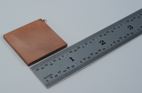
Figure 2. Heat pipe thermal ground plane.
Benefits of the heat pipe TGP
The heat pipe TGP uses all the same reliable components used in the construction of a cylindrical heat pipe. It also employs a capillary wick structure, typically sintered powder metal, which allows the heat pipe to provide the highest heat flux capability along with the greatest degree of freeze/thaw tolerance and insensitivity to gravitational orientation. The thin, flat structure makes an ideal substrate for mounting electronic devices in packages where vertical space is highly constrained.
The heat pipe TGP represents a proven two-phase cooling approach, where the benefits include very high effective thermal conductivity (500 W/(m.K) to 2,000 W/(m.K) or more, depending on the size of the TGP), extreme reliability, and no moving parts, electrodes, or need for external power, allowing the attached LED device to run cooler as a result of improved heat spreading. A reduction in junction temperature of 20 to 30 deg C through the introduction of a TGP heat spreader versus conduction in low-CTE materials is not uncommon.
As with a traditional cylindrical heat pipe, the TGP transfers and moves heat through the flow of evaporated working fluid so heat can be transported longer distances with less temperature difference than is possible in a solid conductor. In addition, the TGP spreads heat laterally due to its geometry, which makes the TGP a superior heat transport/heat spreading technology. Generally, the larger the TGP (i.e., the longer the heat transport distance and wider area of spreading), the greater the effective thermal conductivity. For a solid material, the thermal conductivity is a fixed, intrinsic property, so transporting more thermal energy or transporting the same energy over a longer distance requires greater temperature difference, which is undesirable for electronic devices and systems.
Depending on the application, designing a heat pipe TGP with a matching CTE can improve cooling while increasing reliability through reduced junction temperature and reduced thermal stress in the bonding material between the TGP and semiconductor. In addition, the TGP substrate can be tailored to more closely match various semiconductor materials, including silicon, silicon carbide, gallium arsenide, and gallium nitride. Heat pipe TGP structures can be effective up to 350 W/cm2. New electronic systems utilizing the TGP-based thermal solution can run at a higher power density than previous systems based on thermal conduction in solid materials without increased weight or complexity.
Bright future for demanding applications
In addition to using heat pipe TGPs for newly designed electrical components and device packages, designers can improve existing LED electronic components that need to fit in tightly constrained spaces such as small, hand-held devices, avionics, and laptop computers. Insertion of TGPs into existing systems can overcome the constraints of size and power while simultaneously reducing the operating temperature of the LED electronic components, or improving the performance of the current thermal management system for handling increased thermal dissipation. In essence, the cost savings is in the extension of the current product life without having to significantly re-engineer it for increased power.
Heat pipe TGPs, based on proven and reliable two-phase cooling technology, can be constructed using a variety of materials and in a range of sizes to surpass many thermal management challenges in various industries and applications. The thin, flat form factor of the TGP makes it ideal for directly mounting LED electronic devices for improved thermal dissipation and reduced interface resistance. From there, design engineers can thermally control electronic components for increasingly demanding military, avionic, and aerospace applications -- including satellite radiator panels, target acquisition systems, remote wing electronics, and navigational avionics -- more efficiently than with traditional cooling methods.
Another cooling alternative
Encapsulated annealed pyrolytic graphite (APG) such as the k-Core system is another LED thermal management option. APG is hermetically sealed within a structural shell, often referred to as the encapsulant, made of traditional materials like aluminum, copper, beryllium, ceramics, or composites, and is three to five times as conductive as copper with less density (g/cm3) than aluminum. Encapsulated APG solutions have no moving parts, so they are compatible with standard finishing and processing manufacturing steps, giving thermal engineers design flexibility while addressing concerns about durability and maintenance. Unlike heat pipes that rely on two-phase heat transfer using a working fluid, APG is a system that relies on conduction heat transfer. APG is an excellent solid conduction material and has an in-plane conductivity of 1,700 W/(m.K) which is greater than four times that of copper (~390 W/(m.K)).
The coefficient of thermal expansion (CTE) offered by encapsulated APG can be tailored or matched to a specific application, allowing dissipation of dramatically increased heat fluxes by allowing direct attachment to the LED and minimizing thermal resistance. Combining high thermal conductivity of APG with an easily tailored CTE encapsulation material allows engineers to create solutions for high-powered LED applications while keeping weight and footprint under control, thus allowing more space and weight to be devoted to power and other system elements, bringing an increasing amount of LED power to smaller spaces. In addition, encapsulated APG technology performs well under extreme temperatures and demanding stress, load, and vibration conditions, making it ideal material for military uses.
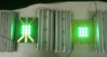
Figure 3 shows the results of using encapsulated APG inside a printed wiring board to create a high-conductivity PWB (HCPWB). At 100 mA (13.2 watts) the HCPWB is showing almost two times the Lux readings of the standard PWB. The standard PCB shows the Lux readings peaking and then falling off at the highest current levels, indicating that the excessive heat is preventing the additional current from creating additional light.
In general, encapsulated APG lowered LED package temperature by nearly 20 deg C, allowing the LED array to run significantly cooler than a standard printed wiring board (PWB). With a 17 deg C/W resistance to the junction temperature of the individual LEDs, the standard PWB configuration would require significant device de-rating to avoid overheating and/or short-life of the devices. Copper-clad APG provides a highly conductive core (up to 1,200 W/(m.K)) that can serve as a ground or power plane. When integrated within a PWB, this will result in a PWB with thermal conductivity greater than 300 W/(m.K) (15 times a standard PWB).
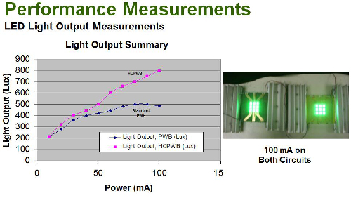
Figure 3: Encapsulated APG used in a PWB.
Another significant advantage to utilizing encapsulated APG as a thermal management solution is that it is typically a custom solution: The heat transfer system is designed for a specific application by an expert engineering team. For design engineers working on critical military technology, this customization provides a level of confidence in the power and efficiency of the project.
Potential defense application
Figure 4 shows a unique potential application of LEDs in defense: replacing standard chemical flares with advanced LED lighting technology. A chemical flare is a type of pyrotechnic that produces brilliant light without an explosion. These traditional flares face reliability issues, especially after long-term storage. Battery-powered LED flares offer higher reliability and provide a lot of light in minimal space. When deployed from a parachute or from a helicopter, the LEDs illuminate a wide area of the ground, offering an important benefit in military applications. Plus, the LED is recoverable and reusable, therefore more cost efficient and resource effective. In this case, the thermal solution would be similar to that shown in Figure 1. The heat pipes contact the LEDs directly and transport their heat to natural convection fins. As the flare is dropping, the air circulates through the fins and removes the heat.
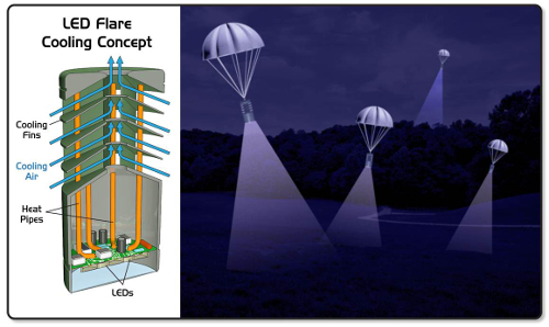
Figure 4: LED flare concept.
Because LEDs can be designed to operate on various wavelengths, they can also be used for infrared lighting for night-vision goggles, vehicle lighting, or security lighting, offering a valuable tactical advantage in military applications.
Another potential use of LEDs is on the ultraviolet wavelength, where the light can be used for water treatment devices or sterilization of surgical equipment for field units. When space and resources are limited and sanitization is of utmost importance, this is an especially useful option.
Conclusions
Because of the long list of engineering, quality, and financial concerns and considerations when designing LED-based lighting applications (such as power consumption, operating efficiency, product reliability, operating life, size, and cost), there is no one-size-fits-all thermal management technique. A number of thermal technology options and materials must be explored, with the specific application requirements driving selection and implementation.
For many high-power, space-constrained military LED lightening applications, custom thermal management solutions using passive thermal management technologies are an ideal option. Passive thermal technologies allow design engineers the flexibility to pack more power into a smaller footprint, thanks to lightweight, flexible designs resulting in higher-quality, more reliable, and longer-lasting lights. In military applications, these benefits translate into LED and resource efficiency, device durability, reliability, and long life, allowing design engineers to meet ever-increasing demands and considerations for custom thermal technology and lighting projects.
Want more information? Go to www.thermacore.com.
Published September 2014
Rate this article
View our terms of use and privacy policy